As a follow-up to my previous post and the information that Frank and Matt provided, I'm providing information on the rudder bearing inspection and gaiter replacement performed on Vento Solare (Hull 266)
Bottom line - The rudder bearings on hull 266 are Delrin made by Jefa. There was absolutely no wear or corrosion. The gaiter was replaced, and since the rudder was out, the gaiter purchased was already glued in the conical shape required. If the rudder was left in place, a split gaiter can be purchased and replaced by gluing a seam once it is wrapped around the rudder shaft. Since this is the first time the rudder has been pulled on hull 266, I now have piece of mind knowing that unless there are future symptoms of a rudder bearing problem, I do not need to remove the rudder. and if needed, can replace the gaiter in place.
Here is a view from below of the lower Delrin rudder bearing
 Procedure to Remove the Rudder if the Jefa Rudder Bearings are used (may differ for Edson Aluminum Bearing installations).
 This assumes the boat is hauled and on a keel block 6 inches tall.
Gaiter
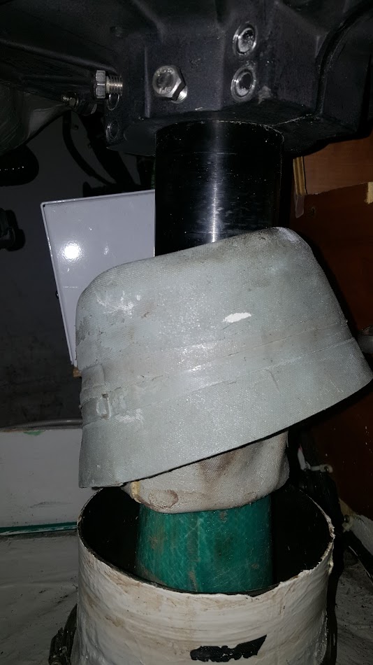
The gaiter is held on a hose clamp on the rudder shaft and another on the rudder tube. Loosen these clamps.
Tiller Arm - this is only installed if you have an autohelm driven below decks
Picture of the tiller arm on hull 203 that was cracked, but shows the bolt arrangement.
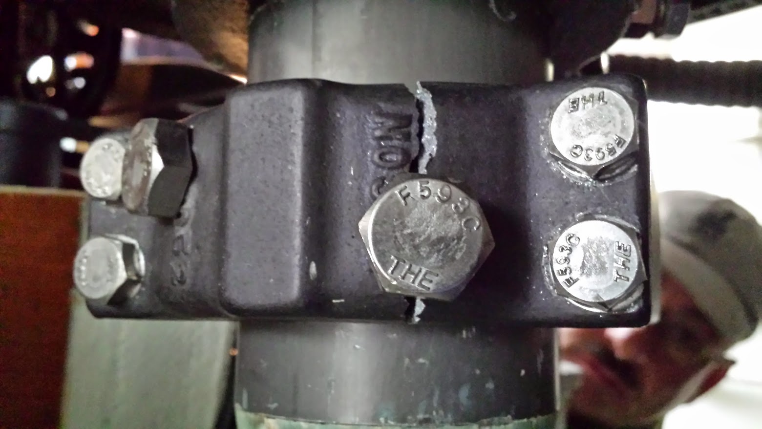
1. If you have a rudder angle sensor, it is most likely attached to the tiller arm. The sensor must be disconnected from the tiller arm in order to remove it.
2. The autohelm connection is made via a rose joint. Pull the locking ring and washer and slide the drive mechanism off the rose joint. If the rose joint is stuck, you can unscrew it from the tiller arm, and once removed clean and service the rose joint.
3. Loosen the autohelm tiller arm (if installed) which is located below the radial drive wheel and above the top of the gaiter. Typically the tiller arm is held on with four 9/16" hex head stainless bolts that join the two split sections clamped around the rudder shaft. There are two additional 9/16" bolts that lock the arm on the shaft to prevent it from twisting. Remove these bolts too.
4. Once all the bolts are removed, tap the tiller arm with a rubber mallet to separate it from the rudder shaft.
Radial Drive Wheel
Photo of radial drive wheel from above and Upper bearing lower glide ring with locking collar

Photo of radial drive wheel from below with Gaiter loosened
1. Loosen the steering cable and leave it connected to the radial drive wheel. The steering cables are terminated to eye bolts threaded through to the bottom of the radial drive wheel. On each eye bolt has two 1/2" hex bolts and a washer. The two hex bolts lock in place to prevent movement after the cable is adjusted. Unlock the outer hex nut and back it off. There is no need to remove the nut, just make it so it is loose and near the end of the threaded section. Unscrew the inner nut to loosen the cable.
2. Loosen the radial drive wheel which is located below the upper bearing and above the top of the gaiter. Typically the drive wheel held on with four 9/16" hex head stainless bolts that join the two split sections clamped around the rudder shaft. There are also two additional 9/16" bolts that lock the arm on the shaft to prevent it from twisting. Remove these bolts too. There are two 7/16" hex head bolts located just inside the outer edge that hold the radial drive wheel halves together. Remove these two bolts that are installed with lock washers and a hex net.
3. Once all the bolts are removed, tap the radial drive wheel with a rubber mallet to separate it from the rudder shaft. Position the half with the cable connected aft of the rudder tube with the cables on either side. The rudder should now be free to turn, independent of the wheel and steering mechanism.
Upper Bearing - Lower Glide Ring (these are ball bearings)
In the photo above, the black collar above the radial drive wheel locks the lower glide ring in place. The lower glide ring and collar provide a smooth load bearing surface that prevents the rudder shaft from moving upwards.
1. There are three equally spaced 4mm allen screws positioned around the locking collar. Loosen these screws so the collar is free, but do not remove the screws.
The locking collar and glide ring will slide off the top of the rudder shaft when the rudder is removed.
Top Bearing Locking Collar and Glide Ring - Final Step of Rudder removal
Caution - The rudder is free to fall out of the boat when this step is performed. Make sure the rudder is supported. This is a two person job!
Photo of upper bearing locking collar (located at Emergency Tiller attachment point) - the allen screws holding this in place can't be seen but are located around the periphery of the locking collar which is placed over the rudder shaft.

1. Block the bottom of the rudder using a scissors jack and wood blocks. Position a foam pad or towel under the rudder so it doesn't get damaged. Raise the jack so it just supports the rudder.
2. Remove the cover on deck to gain access to the rudder shaft where the emergency tiller attaches.
3. With one person below and one person above, have the person below hold the rudder and make sure the rudder supports do not slide out. The person above will loosen the three equally spaced 4mm allen screws positioned around the locking collar. Loosen these screws so the collar is free, but do not remove the screws. The rudder is now free to be removed.
4. Lower the scissors jack approximately 1 inch. If the rudder does not drop down, use a rubber mallet an tap where the emergency tiller is connected. The rudder will break free. Make sure the second person constrains the rudder and jack so it does not slide out.
5. Once the rudder is free, one person helps hold the rudder below the boat while the other moves the scissors jack and blocks so the rudder may be slid down. The rudder will slide down with sufficient clearance to remove the rudder shaft from the boat before the bottom of the rudder reaches the ground.
When the rudder is removed it is a great time to clean up and inspect all the parts. Use soap, water and a brush to clean and flush the lower rudder bearing. Do NOT use any lubricants on the Delrin bearings or rudder shaft.
Rudder installation is the reverse of the above procedure. The process requires that the rudder shaft be partially inserted in the boat so the gaiter, upper bearing lower glide ring and locking collar can be slid on. Once these are on the shaft, the rudder is jacked in position and locked in place by the top bearing and locking collar. The allen screws on the locking collars should be set with blue (non-permanent) Loctite and set so they are aligned with the original dimples that are scored on the rudder shaft. This is the same for all other assemblies clamped to the rudder shaft. Make sure the assemblies are aligned so that screws used to lock an assembly in position on the rudder shaft are precisely located to the original positions when removed.